IP65 enclosures breathe: how AS-B stops moisture
Introduction — an invisible problem with high cost
Moisture is one of the most underestimated failure factors in industrial electronics, outdoor instrumentation, and any equipment protected by an enclosure said to be “sealed”. Slow PCB corrosion, connector oxidation, sensor drift, intermittent failures from cold-start condensation, dielectric breakdown: the list is long, and the cumulative cost even longer — a single field service return in a remote area can wipe out the margin on hundreds of units sold.
Yet a widespread belief persists, even among seasoned integrators: “I’ve fitted an IP65 enclosure, it’s sealed, I’m safe”. This belief is wrong, and it is wrong for a simple physical reason that we will demonstrate: an IP65 enclosure protects against liquid water and dust, but it does not — and structurally cannot — protect against water vapor. Vapor crosses seals and cable glands by molecular diffusion, slowly but inexorably, until the inside of the enclosure equilibrates with ambient humidity.
This article demonstrates the phenomenon by measurement, quantifies it with a simple physical model (the enclosure’s “time constant”), shows how to bridge an accelerated chamber test to an on-site lifetime prediction, and explains why So Sponge’s AS-B technology is, to our knowledge, the most durable and compact solution on the market for this problem.
1. IP65 does not mean “vapor-tight”
The IP rating, defined by IEC 60529, qualifies two things: ingress of solid bodies (first digit) and ingress of water in liquid form (second digit). IP65 guarantees protection against dust and against water projected by low-pressure jets. IP67 adds resistance to temporary immersion, IP68 to prolonged immersion.
Nowhere does the standard address water vapor. For a simple reason: vapor is not a fluid in the strict sense, it is a gas that obeys the laws of diffusion. And every sealing material used in industrial enclosures — EPDM, NBR, silicone elastomers, O-rings, foam gaskets, cable glands — is permeable to water vapor to varying degrees. At molecular scale, polymer is a porous medium for H₂O molecules, which traverse it by dissolution-diffusion (Henry’s and Fick’s laws).
Concrete consequence: every IP65 enclosure sees its internal partial vapor pressure tend, eventually, toward the external partial vapor pressure. The question is never “will my enclosure take on humidity?” but “how fast?” and “at what equilibrium level?“.
2. Enclosure “breathing”: a quantifiable phenomenon
To characterize this phenomenon, a reference experiment is performed: a temperature and humidity sensor is placed inside the empty enclosure, the assembly is installed in a climate chamber, and a stable external condition is imposed — for example 35°C and 100% relative humidity, an aggressive condition representative of an accelerated tropical test. Internal humidity is then logged over time.
The typical result is a first-order exponential curve:
RH_int(t) = RH_ext − (RH_ext − RH_0) · exp(−t/τ)where:
- RH_ext is the external relative humidity (the chamber setpoint, here 100%)
- RH_0 is the initial humidity inside the enclosure at test start
- τ (tau) is the time constant characteristic of the enclosure, expressed in hours or days
This equation is the analytical solution of the mass balance:
V · dC/dt = K · A · (C_ext − C_int)where V is the enclosure volume, A its wall surface area, K the average permeance to water molecules, and C the mass concentrations of vapor. The time constant equals τ = V / (K·A) — it depends only on the enclosure’s geometry and materials, not on external conditions.
This is the equation Fick established in 1855, and which today describes gas diffusion through biological membranes, food packaging, and electronic enclosures alike.
3. Practical reading of τ: the enclosure’s vapor-tightness signature
The time constant τ reads as the vapor-tightness signature of the enclosure: the larger τ, the tighter the enclosure; the smaller τ, the faster it breathes. It is an intrinsic property of the enclosure (material, seals, cable glands, geometry), independent of external conditions.
To give orders of magnitude observed in practice:
- a low-end ABS enclosure with foam gasket → τ from a few hours to 1 day
- a polycarbonate IP65 industrial enclosure with EPDM gasket → τ of a few days
- a die-cast aluminum IP67 enclosure with molded silicone gasket and IP68 cable glands → τ of several weeks
- a hermetically sealed metal-glass enclosure (aerospace, medical) → τ of several years
Quick reading rule: the practical “near-equilibrium” target corresponds to about 3·τ (95% of the path traveled). Beyond 5·τ, the system is considered equilibrated (>99%). For an enclosure with τ = 11.5 days, operational equilibrium is reached in just over a month under chamber conditions, and practical saturation in about two months.
For readers who want mathematical precision: τ is defined as the time at which the system has traveled exactly 1 − 1/e ≈ 63.2% of the gap toward equilibrium. This convention is universal in physics of first-order systems (RC circuits, transient thermal, chemical kinetics). The table below lets you convert any humidity target into an effective delay:
| Multiple of τ | Fraction of equilibrium reached |
|---|---|
| 0.7·τ | 50% |
| 1·τ | 63.2% |
| 2.3·τ | 90% |
| 3·τ | 95% |
| 4.6·τ | 99% |
Measuring τ on one’s own enclosures is therefore a basic engineering act, which should precede any choice of humidity management solution — just as one measures contact resistance or quiescent power consumption before specifying a product.
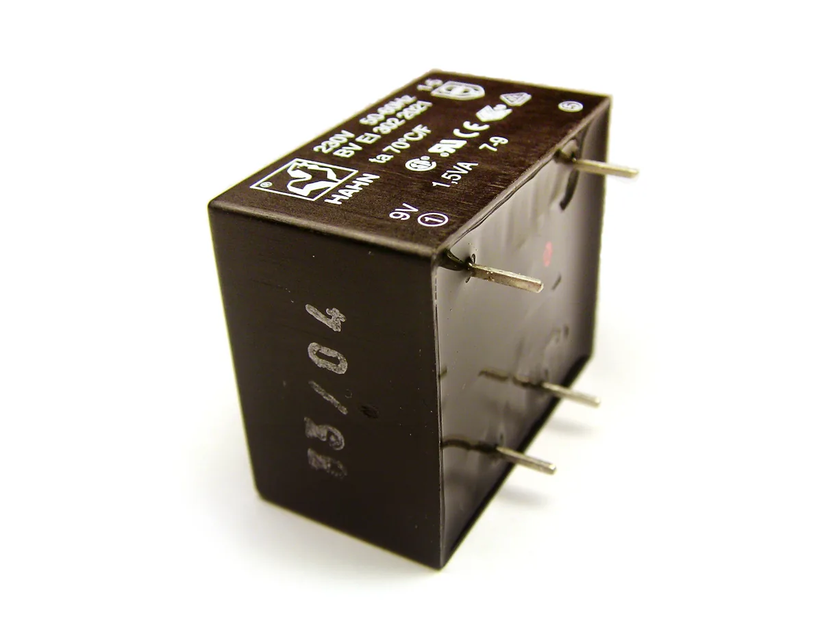
4. Practical case: blank test on an industrial enclosure
By way of illustration, here are the results of a blank test performed on a standard IP65 enclosure placed in a chamber at 35°C / 100% RH setpoint, with internal sensor:
- Start: internal RH = 49%
- After 4.6 days: internal RH = 66%
- Exponential fit: R² = 0.996, τ = 11.5 days
The physical model lets us project the rest:
| Internal RH target | Delay since start |
|---|---|
| 80% | ~10 days |
| 90% | ~19 days |
| 95% | ~27 days |
| 99% | ~53 days |
In other words, in less than two months, an empty IP65 enclosure left in a tropical environment sees its interior saturate with humidity. At that point, condensation becomes possible at the slightest nightly temperature drop, and cumulative damage to the electronics begins.
5. From chamber to field: never reason on RH alone
A frequent methodological mistake is to transpose accelerated test numbers directly to field conditions. For precise physical reasons, this shortcut overestimates real-world severity.
The driver of diffusion across walls is not relative humidity, it is the absolute vapor density (g of water per m³ of air), or equivalently the partial vapor pressure. This quantity depends very strongly on temperature, via the Magnus equation:
P_sat(T) = 6.1078 · exp(17.27·T / (T + 237.3)) in hPaAt 100% relative humidity, air contains:
| Temperature | Saturated vapor density |
|---|---|
| 10°C | 9.4 g/m³ |
| 20°C | 17.3 g/m³ |
| 25°C | 23.1 g/m³ |
| 35°C | 39.5 g/m³ |
| 40°C | 51.2 g/m³ |
| 50°C | 83.0 g/m³ |
A 35°C / 100% environment (chamber test) thus contains more than double the water per m³ of a 25°C / 80% environment (French coastal climate in summer), and nearly five times that of a tempered indoor environment at 22°C / 60%. The moisture flux entering the enclosure is proportional to this absolute density, so the real-world lifetime of a field protection is typically 3 to 5 times longer than the accelerated test suggests.
This is exactly the philosophy of “85°C/85%” tests in consumer electronics: aging is artificially accelerated so that a few weeks of test yield information equivalent to several years of normal use.
6. Why classical solutions reach their limits
Faced with enclosure breathing, several historical approaches exist, each with its limits:
Silica gel sachets. The most widespread solution, but with rapid saturation in humid environments, a re-release risk on temperature drop, and the need for periodic replacement. The detailed silica gel / SRD comparison is treated in section 9, since it is the most frequent technical objection in design offices.
Ventilation membranes (Gore-Tex and equivalents). Allow pressure equalization without letting liquid water in. But they do not stop vapor — on the contrary, they let it through freely. They prevent condensation by “mechanical breathing” of the enclosure during thermal fluctuation, but do not address the underlying problem: the inside still equilibrates with the outside over time.
Anti-condensation heaters. Maintain the enclosure above the dew point through Joule heating. Effective, but constant energy consumers (typically 5 to 30 W per enclosure), and unsuitable for autonomous applications or strong energy constraints (off-grid solar, battery IoT, mobile equipment).
Inert-gas sealed enclosures. The ultimate but expensive solution, reserved for aerospace, medical, or scientific instrumentation. Inapplicable to standard industrial production.
A passive, durable, compact and economical solution was missing for the standard B2B industrial segment: this is what AS-B fills.
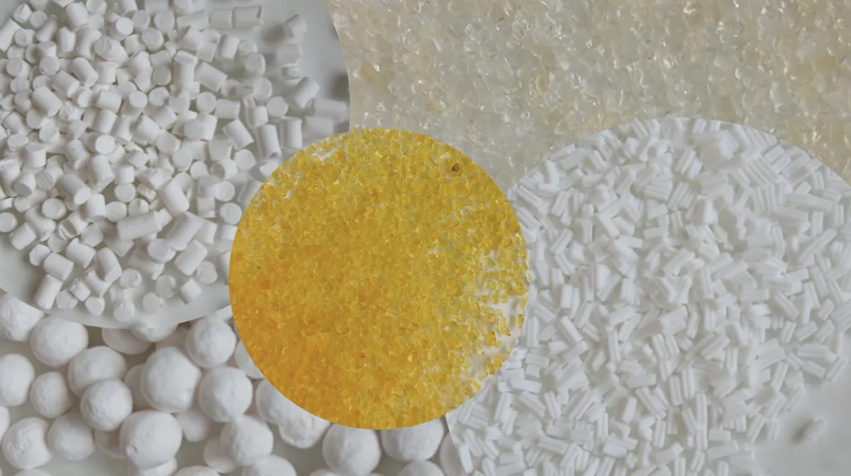
7. AS-B: a passive sticker with very high useful capacity
AS-B is a functional adhesive developed by So Sponge from SRD, a patented self-regenerating desiccant based on mesoporous aluminum oxide. The principle is simple: the sticker adheres to any flat surface inside the enclosure (wall, bottom, lid), and adsorbs the water vapor entering by diffusion. It operates continuously, without energy consumption, and without maintenance over the equipment lifetime.
Three technical features set it apart:
Useful capacity concentrated on the risk zone. SRD adsorbs up to 1 gram of water per gram of active material under typical operating conditions, and — as detailed in section 9 — most of this capacity is available precisely in the high-humidity zone (60-90% RH) that precedes condensation. On this risk zone, SRD offers approximately 8 times the useful capacity of silica gel. An AS-B sticker loaded at 200 g/m² thus stores up to 200 g of water per m² of installed surface.
Spontaneous regeneration. Unlike conventional desiccants which must be baked at 120-200°C to release adsorbed water, SRD regenerates spontaneously during the dry phases of the ambient cycle — without any thermal input, by mere evolution of surrounding humidity. This property significantly extends the useful lifetime in variable-humidity environments, as opposed to strong-bond desiccants which remain saturated once their capacity is reached.
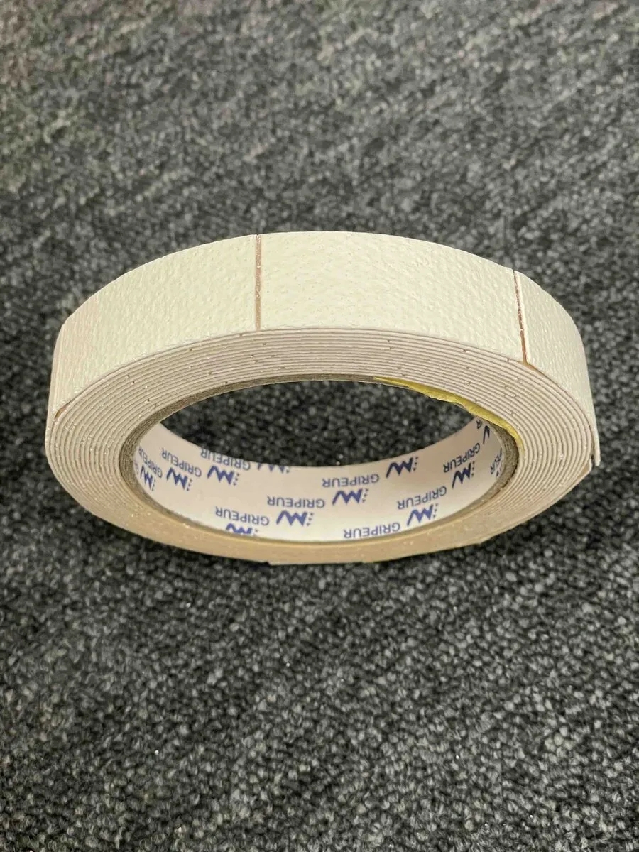
Adhesive format. The sticker integrates without mechanical modification of the enclosure, no dead volume, no extra fixture. Compatible with existing production lines, it is applied in seconds during final assembly.
8. Sizing method: how much AS-B for my enclosure?
8.1 Define the target: which internal humidity level to tolerate?
Before any calculation, the internal RH threshold the protection must guarantee must be set. This threshold depends on the protected equipment’s sensitivity:
| Target RH_int | Typical use case |
|---|---|
| ≤ 90% | Strict minimum — prevent condensation by a few-point margin below dew point. Acceptable for low-sensitivity consumer electronics. |
| ≤ 70% | Recommended operational threshold for industrial electronics and outdoor instrumentation. No accelerated corrosion, comfortable safety margin. |
| ≤ 60% | Sensitive applications (relays, gold-plated contacts, optoelectronics, precision sensors). |
| ≤ 30% | Critical applications (bare semiconductors, precision optics, metrology). |
The §8.4 example and §8.5 sizing table below are computed for the strict anti-condensation threshold ≤ 90% — the physical minimum to prevent droplet formation on cold surfaces. This is the most compact dimensional baseline. For applications requiring long-term electronics reliability (industrial consensus at 70%, sensitive sensors at 60%), see the sensitivity analysis §8.6 which details how the required surface evolves with the chosen threshold.
8.2 Sizing formula
The water flux entering the enclosure is governed by Fick’s law: it is proportional to the vapor density gradient between outside and inside, and inversely proportional to the enclosure’s time constant τ. With internal RH maintained at target RH_int:
Φ_annual = (V / τ) · ρ_sat(T_field) · (RH_ext − RH_int) · 365 [g/yr]with:
- V: internal enclosure volume (m³)
- τ: measured time constant of the enclosure (days)
- ρ_sat(T): saturated vapor density at field temperature (g/m³, see Magnus table in section 5)
- RH_ext and RH_int: relative humidities as fractions (0 to 1)
The AS-B sticker surface required to absorb this flux for L years is then:
A_sticker = (Φ_annual · L) / (σ · 200) [m²]with σ = 1 g/g (SRD mass capacity) and 200 g/m² the surface load of the AS-B sticker.
8.3 Worst-case approach for sizing
Under field conditions, ambient humidity varies over the year and the day. To guarantee that RH_int stays under threshold at all times, sizing is done on the most unfavorable condition likely to be encountered — typically the cumulative “high T × high ambient RH” of summer or tropical peaks, not the annual climatic average.
This is a conservative approach that guarantees performance under the worst conditions. In practice, the real AS-B lifetime will be significantly higher than this specification, because during the dry phases that constitute the majority of the year, the material regenerates partially — the cyclic mechanism is detailed in section 9.2. The exact magnitude of this gain depends on the climatic variability of the installation site and can be quantified by the test protocol described in section 9.4.
8.4 Worked example
Case: 1 L industrial enclosure, measured τ = 11.5 days, target lifetime 5 years, French coastal summer operating environment. Design peak retained: 28°C / 95% RH. Strict anti-condensation target: RH_int ≤ 90% (minimum threshold to prevent condensation; for more protective targets, see §8.6).
ρ_sat(28°C)        = 27.2 g/m³
Effective ΔRH      = 0.95 − 0.90 = 0.05
Φ_annual           = (0.001 / 11.5) × 27.2 × 0.05 × 365 = 0.043 g/yr
Total water 5 yrs  = 0.22 g
A_sticker          = 0.22 / (1 × 200) = 0.0011 m² = 11 cm²
That is a postage-stamp format (11 cm²), to be applied to any internal face of the enclosure, for 5 years of anti-condensation protection in a worst-case French coastal scenario — and significantly more in practice thanks to the dry phases between peaks. To target a lower RH_int (long-term electronics reliability), see the sizing table §8.5 (based on the recommended 70% threshold) and the sensitivity analysis §8.6.
8.5 Sizing table
AS-B surface required for a 1 L enclosure (τ = 11.5 d, σ = 1 g/g, RH_int ≤ 90% strict anti-condensation) according to environment and target lifetime. Design peak retained in column 2.
| Environment (worst case) | T / RH | 1 yr | 5 yrs | 10 yrs |
|---|---|---|---|---|
| Extreme test chamber | 35°C / 100% | 6 cm² | 31 cm² | 63 cm² |
| Chronic tropical | 32°C / 95% | 3 cm² | 13 cm² | 27 cm² |
| French coastal summer | 28°C / 95% | 2 cm² | 11 cm² | 22 cm² |
| Tempered French outdoor | 22°C / 95% | 2 cm² | 8 cm² | 15 cm² |
Commercial reading: at the strict anti-condensation threshold, a very compact patch suffices in most cases. A postage-stamp format (~3 cm²) protects a 1 L enclosure for one year in a chronic tropical climate; 11 cm² is enough for 5 years in a worst-case French coastal scenario; and 63 cm² (equivalent to a half-credit-card) protects for 10 years even in an extreme 35°C/100% chamber. To target a lower RH_int (long-term electronics reliability at 70%, sensitive applications at 60%), multiply the above surfaces per the §8.6 analysis.
To visualize the surface in question: a 1 L cubic enclosure measures about 10 × 10 × 10 cm, i.e. a projected surface of one face of 100 cm². A business-card sticker (50 cm²) thus occupies 50% of one inner face, and only ~8% of the total inner surface area of the enclosure (6 faces × 100 cm² = 600 cm²):
8.6 Influence of the chosen RH_int threshold
The choice of protection threshold has a direct impact on the required surface. For the same case (1 L, 5 yrs, French coastal summer 28°C/95%):
| Target RH_int | AS-B 5-yr surface | Use case |
|---|---|---|
| ≤ 90% | 11 cm² | Strict anti-condensation |
| ≤ 80% | 32 cm² | Electronics reliability margin |
| ≤ 70% | 54 cm² | Default recommendation |
| ≤ 60% | 75 cm² | Sensitive applications |
Going from 90% to 60% multiplies the surface by 7. This illustrates the importance of precisely specifying the target threshold at project kickoff, in line with the protected equipment’s sensitivity — rather than oversizing by default.
9. Why not oversized silica gel?
The objection is legitimate and comes up systematically in design offices: if sizing relies solely on a total mass of water to absorb, then any desiccant suffices provided you put enough of it. With silica gel reaching 35-40% peak mass capacity, it would “suffice” to put about 2.5 to 3 times more mass to absorb the same annual flux and obtain the same lifetime. Mathematically, that’s correct. Physically, it’s wrong for three reasons that the manufacturer’s datasheet does not always reveal.
9.1 Isotherm shape: where does the material capture humidity?
The adsorption isotherm describes the amount of water captured as a function of ambient relative humidity. Its shape determines the desiccant’s real usefulness for the problem at hand — not just its total capacity.
Silica gel exhibits a so-called type I isotherm: it adsorbs heavily at very low humidities (significant capture from 10-20% RH), reaches a plateau quickly, and captures little beyond. Consequence: a silica gel sachet placed in a dry enclosure saturates immediately on the residual humidity of factory-packed air. A significant fraction of its capacity is consumed well before the problem (RH > 60%) arises. And once the plateau is reached, its residual capacity for the risk zone is low.
SRD by contrast exhibits a step isotherm characteristic of mesoporous capillary condensation: it adsorbs almost nothing below 60% RH, then captures massively between 60% and 95% RH by capillary condensation in pores. Consequence: all its capacity is available precisely in the zone where the problem occurs — the high-RH zone preceding condensation and corrosion.
On the useful 60-90% RH zone, i.e. the truly relevant zone for equipment protection, SRD offers about eight times the mass capacity of silica gel. Silica gel’s total capacity caps at 35-40% of its weight in water under the most favorable conditions (high humidity, cool temperature), i.e. a raw ratio of about 1 to 3 vs SRD; but when integrating only on the risk zone, the gap widens to a factor of 8.
Methodological note. The ×8 factor communicated by So Sponge corresponds specifically to useful capacity on the 60-90% RH zone — the zone preceding condensation and which determines the effective lifetime of a protection. On the total capacity integrated from 0 to 100% RH, the raw ratio is more modest, around ×2.5 to ×3. This is precisely the central argument of this section: total capacity is not the right sizing parameter; what matters is useful capacity on the risk zone — and that is where SRD distinguishes itself.
9.2 Spontaneous regeneration: total capacity vs cyclic capacity
The second differentiator is adsorption reversibility — and one must be precise here about what this property does, and what it does not, because intuitive reasoning misleads.
What regeneration does not do. It does not slow down vapor entry into the enclosure. The flux crossing the seals is governed by Fick’s law and depends only on the vapor pressure gradient between outside and inside, and on the permeance of sealing materials. No desiccant placed inside has any action on this wall-side flux. Better (or worse, depending on viewpoint): a highly effective desiccant that keeps RH_int very low maximizes the gradient and therefore makes vapor enter faster, not slower. The right argumentative reflex is therefore never to “delay entry”, it is to durably absorb what enters while avoiding premature saturation.
What regeneration actually does. It changes the nature of the annual water balance in the material. Let us pose the two fluxes that govern this balance over a given period:
Net accumulated water = ∫ flux_in(t) dt − ∫ flux_desorbed(t) dtFor silica gel at ambient T, the second term is zero: water is trapped by strong adsorption (release only at 100-300°C in an oven). All entering water accumulates until saturation. Useful lifetime is capped by total sachet capacity divided by mean inflow flux — regardless of ambient fluctuations.
For SRD with a step isotherm and hysteresis, the second term is non-zero in any climate with variable humidity. When ambient RH drops below the desorption threshold (typically after a humid phase, following a day/night cycle, or at the passage of a dry season), the material releases the accumulated water back outside via the same seals that let it in. SRD uses the enclosure’s seals in both directions: in during humid phases, out during dry phases.
Consequence on the annual balance. In a typical European temperate climate where ambient RH oscillates frequently across the SRD thresholds, the net annual accumulation of an SRD is far below that of a silica gel of equivalent mass, even zero in sufficiently variable climates. This is why we speak of cyclic capacity (or working capacity) for SRD, as opposed to the total capacity of a saturable consumable like silica.
This distinction is fundamental for long-term sizing. A silica gel sachet correctly calibrated for 1 year will need to be replaced at 1 year, regardless of climate quality. An AS-B sticker correctly calibrated for 1 year in worst case will in practice last longer in a variable climate, because its useful capacity reconstitutes partially at each dry cycle. The sizing in section 8 should therefore be read as a pessimistic floor for SRD in real-world environments — a guaranteed minimum rather than an average expectation. Precise quantification of this gain for a given site requires the experimental measurement described in section 9.4.
9.3 Kinetics: capturing as fast as humidity enters
The third differentiator is capture speed — a parameter that never appears on datasheets but determines whether protection is effective or only nominal.
If the desiccant captures more slowly than vapor enters, internal RH transiently rises above the condensation threshold during humid episodes (storm, morning fog, water cleaning, cold start). Once condensation has started on the cold surfaces of the enclosure, the damage is done — regardless of whether the desiccant eventually dries the air once conditions stabilize.
A desiccant’s kinetics depends on its porous structure and the specific surface area accessible to vapor. Silica gel works by monolayer adsorption in narrow pores, with relatively slow gas diffusion toward deep active sites. SRD works by capillary condensation in mesopores that are wider and more accessible, allowing vapor to reach active sites quickly and condensation to start as soon as the RH threshold is reached.
In real-world conditions, SRD therefore reacts significantly faster than silica gel to ambient humidity variations — a critical advantage for handling transients (sudden temperature changes, seasonal humidity, periodic ventilation).
9.4 How to demonstrate the difference experimentally
The three differentiators above can be revealed by a simple, reproducible protocol that any design office can replicate to validate against its own field conditions.
Protocol — cyclic test in climate chamber.
Two identical enclosures are each equipped with an internal RH+T sensor. One receives an AS-B sticker, the other an equivalent mass of silica gel in sachet form (e.g., SRD mass calculated for 1 year of protection × 3 to equalize raw capacity). Both enclosures are placed together in the chamber, subjected to the same ambient cycle — for example:
- 8 hours at 30°C / 85% RH (humid phase)
- 16 hours at 25°C / 40% RH (dry phase)
- repeated over several weeks
Recording both internal RH then reveals three distinct signatures:
- RH peak during the first humid phase — lower for SRD (fast kinetics) than for silica (slow kinetics). Direct demonstration of differentiator 9.3.
- Drift of mean RH over cycles — practically nil for SRD (it regenerates during dry phases), positive and growing for silica (accumulation is cumulative). Direct demonstration of differentiator 9.2.
- Date of silica “breakdown” — moment when the silica enclosure’s mean RH durably crosses the 60% threshold, sign that the material is saturated. The SRD enclosure pushes this breakdown significantly further in time under cyclic climate, the exact gap being determined by test duration and the imposed cycle nature.
This dual signature — lower transient peak and lower baseline drift — is the direct physical proof of SRD’s superiority in real-world conditions. It is observable over a few weeks of testing, a delay compatible with a product evaluation cycle in a design office.
9.5 Summary: four parameters, not one
The comparison between desiccants therefore does not reduce to a total absorbable water mass. It plays out on four parameters simultaneously:
| Parameter | Silica gel | So Sponge SRD |
|---|---|---|
| Total capacity (integrated over 0-100% RH) | 35-40% peak | ~100% by mass |
| Useful capacity over 60-90% RH | Low (already saturated) | Maximum (×8 vs silica) |
| Regeneration at ambient T | No | Yes (RH cycles) |
| Annual cyclic capacity | Capped by total capacity | Reconstituted at each dry cycle |
| Capture kinetics | Slow (microporous) | Fast (mesoporous) |
| Long-term behavior | Saturable, to be replaced | Regenerating, extended duration in variable climate |
Oversizing a silica gel sachet to match the raw capacity of an AS-B sticker is mathematically possible — but it does not catch up the poor distribution of capacity on the isotherm, nor the absence of regeneration, nor the slower kinetics. Ultimately, for effective protection over 5 or 10 years in a variable environment, no oversizing of silica gel reproduces the behavior of a passive AS-B sticker.
It is this combination of properties — and not mass capacity alone — that constitutes the technical value of SRD.
Conclusion — rethinking the humidity specification
The industrial market has long treated humidity as a secondary topic, managed by silica gel sachets to be replaced periodically, or by the erroneous belief that an IP65 suffices. The physics of molecular diffusion imposes a different reading: every enclosure breathes, the only lever is the adsorption capacity installed inside, and that capacity must be sized starting from real field conditions, not chamber spec.
AS-B offers a solution designed for this reality, distinguished from silica gel not by mass capacity alone, but by three combined properties: a step isotherm that concentrates useful capacity in the risk zone (60-90% RH), a spontaneous regeneration at ambient temperature that significantly extends lifetime in variable environments, and a fast kinetics that handles humidity transients before they cause condensation. All in an adhesive format integrable without mechanical modification of the enclosure.
Sizing is analytical, transparent, and lets a design office specify a protection lifetime over 1, 5 or 10 years depending on the chosen format — without energy, without maintenance, without re-release risk.
To characterize τ on your own enclosures, simulate a field projection, or receive a personalized sizing for your use case: contact the So Sponge team.
This article is published by So Sponge, a French deeptech based in Lyon, specialized in passive humidity control solutions based on patented mesoporous materials. SRD technology is licensed from Pulsalys, the Lyon Saint-Étienne tech transfer office, from research conducted at Université Claude Bernard Lyon 1 and IFP Énergies Nouvelles.