IP65 solar inverters: the underestimated humidity risk
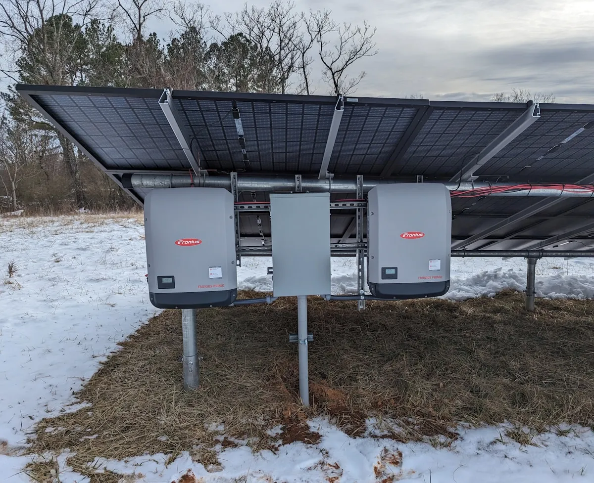
In a photovoltaic installation, the inverter plays a critical role: it converts the direct current generated by the panels into the alternating current fed to the grid. It is also the weak link. Where solar panels operate efficiently for 25 to 30 years, string inverters have a typical service life of 10 to 15 years — and about one third of them experience their first failure before 15 years [1][2].
Among the factors that accelerate these failures, poorly controlled internal humidity is arguably the most underestimated. Here is why — and how to avoid it.
The inverter: the beating heart — and Achilles’ heel — of your installation
Whether string inverters (for small installations) or central inverters (for large solar farms), this equipment operates around the clock, often in extreme environments: scorching rooftops, abrupt thermal swings, direct exposure to the elements.
Manufacturers protect these devices with an IP65 rating, meant to guarantee sealing against water splashes and dust. But the IP65 rating describes protection against liquid water and particles — it says nothing about managing water vapour or internal condensation. Depending on the design, an IP65 enclosure may be fully sealed or fitted with a membrane vent (pressure compensator); in both cases, internal humidity remains a parameter to manage actively, not a matter resolved by the protection rating alone.
The mechanism: thermal cycling and condensation
Solar inverters undergo significant daily thermal cycles. In full sun, under load, the internal temperature can climb sharply; at nightfall, it drops. This day/night thermal gap is the driver of the phenomenon.
What happens inside the enclosure:
- During the day — Warm air loads up with humidity (from the ground, prior rain, or desorption from internal materials).
- At night — The temperature drops. Cooled air can no longer hold as much moisture. When the dew point is reached on the coldest surfaces — circuit boards, transformers, capacitors, contactors — condensation forms.
- The cycle repeats — Each thermal cycle can renew the phenomenon.
This mechanism is not theoretical. Numerical modelling of condensation inside an inverter enclosure confirms that humidity is a significant cause of device failure [3]. And in the field, the failure profile is characteristic: humidity-related insulation faults are often intermittent — the system trips into safe mode early in the morning (dew, dew point reached), shuts down, then operates again by midday once the interior has dried out [4]. It is one of the most recognisable signatures of an internal humidity problem.
This situation is particularly pronounced in coastal, mountainous or humid regions, where outdoor relative humidity regularly exceeds 70–80%.
Humidity in the hierarchy of failure causes
It would be dishonest to present humidity as the No. 1 cause of inverter failures: the reliability-literature consensus identifies thermal stress as the dominant factor for power modules [5]. But humidity holds a far more important place than is generally believed.
An analysis of the stress factors behind power-electronics failures breaks them down as follows [5]:
| Stress factor | Share of failures |
|---|---|
| Temperature (steady-state + cyclic) | 55% |
| Vibration / shock | 20% |
| Humidity / moisture | 19% |
| Contaminants & dust | 6% |
Nearly one failure in five is thus linked to humidity — neck and neck with mechanical stress, and well ahead of dust. For a factor so rarely addressed in standard enclosure design, that is considerable.
The degradation mechanisms: how humidity damages the inverter
Electrolytic capacitor deterioration. This is the Achilles’ heel. Capacitors — particularly aluminium electrolytics — are the leading failure item in inverters: about 30% of failures are attributed to them [6]. Humidity does not act by directly “penetrating the electrolyte”; it degrades the seals and promotes corrosion, which translates into a drop in capacitance and a rise in ESR (equivalent series resistance). The capacitor then generates more heat, and local thermal runaway precipitates its end.
Track and component corrosion. Condensation on circuit boards creates parasitic conductive paths and initiates corrosion of copper traces and solder joints. Small-signal components lose their electrical integrity.
Insulation faults and semiconductor degradation. Humidity reduces insulation resistance, causing leakage currents, safety trips and spurious shutdowns [4]. IGBTs (power transistors), although primarily victims of thermal stress, see their reliability affected by insulation faults in the presence of humidity.
Busbar and connector oxidation. Even protected by IP65, connectors eventually accumulate a thin oxide layer. This increases contact resistance, causing voltage drops, localised heating and, eventually, circuit failure.
Not just the inverter: AC/DC combiner boxes, the blind spot of PV installations
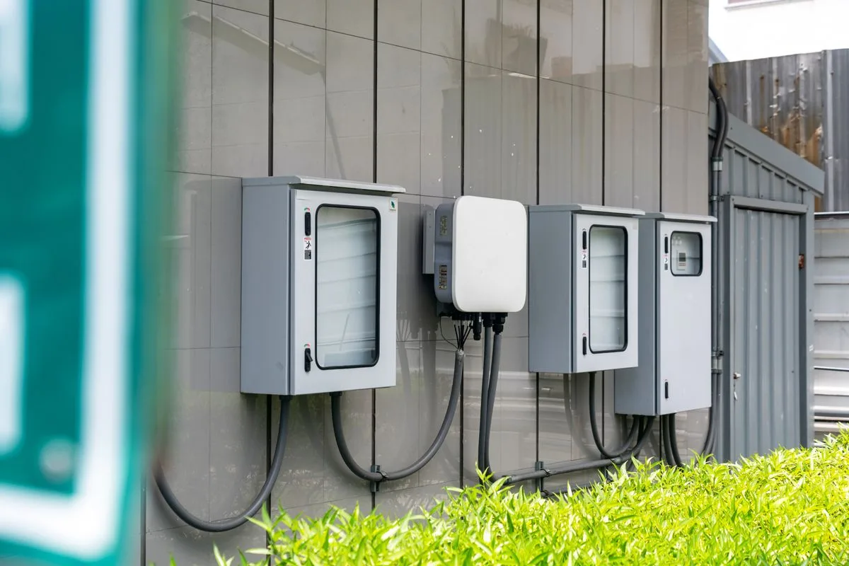
The inverter gets the attention — but between the panels, the inverter and the switchboard sit the DC and AC protection boxes (junction, disconnect and protection enclosures). Feedback from installers and O&M operators converges: these boxes report the same humidity problems as inverters, with three specifics.
ABS enclosures are more affected than metal ones. The polymer’s thermal behavior widens the gap between wall and internal air temperatures: condensation settles in more readily, and moisture typically accumulates at the bottom of the box, out of sight.
The failure chain leads to fire. Humidity corrodes contact points; a corroded or loose connection raises resistance, heats up, and can strike an arc. In the industry’s field experience, a share of PV fire incidents remains unexplained after investigation — internal enclosure humidity is among the plausible contributors. And production lost after an incident is gone for good.
Inspection is yearly, condensation is daily. A box is typically checked once a year; between two visits, condensation works unwitnessed. The treatments observed in the field — compressed air, water-displacing spray, silica gel sachets — are reactive and temporary: they deal with the water already there, not the humidity that returns on the next cycle.
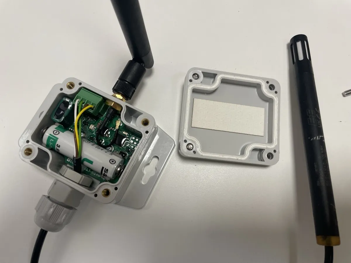
The preventive logic already exists in the trade: fire protection is fitted systematically at installation. A self-regenerating desiccant follows the same logic — a few tens of euros per installation, fitted at the bottom of the box, maintenance-free afterwards: the AS-C ribbon for common boxes of 20 L and above, the AS-B sticker for small boxes (online quote).
Why it matters economically
The inverter is already the component that concentrates the majority of a PV system’s failures. When a third of inverters fail before 15 years [1][2], and an avoidable factor — humidity — accounts for nearly 20% of failure causes [5], controlling internal humidity becomes a direct lever on total cost of ownership: fewer early replacements, fewer maintenance interventions, fewer production losses from spurious safety trips.
The solution: a passive, permanent dehumidifier
This is precisely where So Sponge’s SRD material comes in. The AS-B sticker (and the AS-C tape for larger volumes) is placed inside the enclosure and captures water vapour before it condenses on sensitive components.
Its distinctive feature: it is self-regenerating. During the hot hours of the day, when the inverter heats up, the material returns the captured moisture to the enclosure air, which is then warmer and can hold it without condensing; at night, it is ready to adsorb again. This adsorption/desorption cycle naturally follows the inverter’s thermal cycle — exactly the cycle that causes condensation. Unlike silica gel, which saturates and must be replaced, SRD requires neither replacement nor maintenance.
The SRD material is passive, inert, and does not affect the inverter’s regulatory performance. REACH and RoHS compliance confirmed on request.
Frequently asked questions
Are AC/DC combiner boxes affected as much as the inverter? Yes. Junction, disconnect and protection boxes go through the same day/night thermal cycles as the inverter, with less internal heat dissipation to dry the air. Field reports flag moisture at the bottom of the box and corrosion of contact points as the typical symptoms.
Why do ABS boxes condense more than metal ones? Polymer and metal behave differently thermally: the walls of an ABS box open temperature gaps with the internal air that favor locally crossing the dew point. Metal boxes are not immune — the mechanism is the same.
Can humidity really cause a fire on a PV installation? Indirectly, yes: corrosion of a connection → higher contact resistance → heating → arc risk. That chain is well documented in electrical engineering, and a share of PV fire incidents remains unexplained after investigation. Treating the internal humidity of the boxes removes one link from that chain.
What can be done between two yearly maintenance visits? That is precisely the use case for a passive self-regenerating desiccant: fitted once at the bottom of the box, it keeps the air below its dew point continuously, with no energy and no intervention — where compressed air, sprays and silica gel only treat the symptom on the day of the visit.
Evaluate it on your own inverters
So Sponge provides free samples for B2B technical evaluation and offers a free sizing study for utility-scale deployments.
- Request samples
- Inverter validation programme → sales@sosponge.com
Bibliography
[1] C. Bucher, J. Wandel, D. Joss, “Life Expectancy of PV Inverters and Optimizers in Residential PV Systems”, 2022. Study reporting that about 34% of residential inverters experience their first failure within 15 years of operation.
[2] PV reliability syntheses (comparative service lives): string inverters 10–15 years, microinverters 20–25 years, PV modules 25–30 years.
[3] “Reducing Condensation Inside the Photovoltaic (PV) Inverter according to the Effect of Diffusion as a Process of Vapor Transport”, Frontiers in Heat and Mass Transfer (FHMT), Tech Science Press, 2024. Numerical modelling of condensation in a PV inverter enclosure, identifying humidity as a significant cause of failure.
[4] Documented field feedback on inverter isolation faults: humidity — dew, condensation, coastal moisture — reduces insulation resistance and causes intermittent (typically morning) safety trips.
[5] Analysis of power-module stress factors (reliability-literature synthesis, cited in “A Self-Commissioning Edge Computing Method for Data-Driven Anomaly Detection in Power Electronic Systems”, arXiv:2312.02661, 2023): Temperature 55%, Vibration/shock 20%, Humidity/moisture 19%, Contaminants/dust 6%. The consensus identifies thermal stress as the dominant factor; humidity receives growing attention.
[6] “Grid-Connected PV Inverter Reliability Considerations: A Review”: about 30% of inverter failures result from capacitor degradation (mainly aluminium electrolytics); ~21% attributed to semiconductors and solder joints.
[7] NREL, “Mission Profiles for Humidity Models in the Reliability Testing of PV Inverters”, NREL/CP-5D00-80375. Development of mission profiles to model the impact of humidity on PV inverters, based on field climate data (Cocoa, Florida) compared with industrial and military standards. Institutional reference on inverter humidity reliability.
Transparency note: the service lives and failure shares cited come from published PV reliability studies (references above). The specific performance of the SRD material is based on So Sponge internal testing and datasheets available on request.